-
oceanintr@gmail.com -
08048774841 - Send SMS
- Send Email
Bison False Ceilings
Preferred Buyer From
| Location | Worldwide |
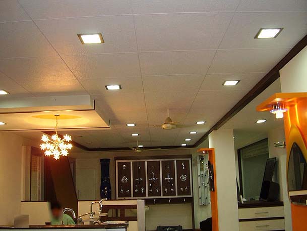
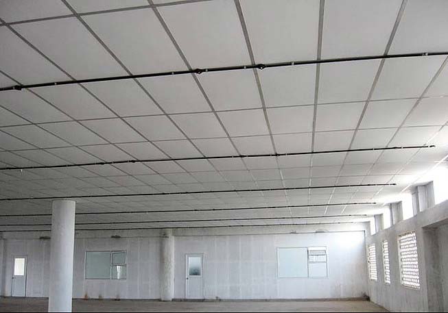
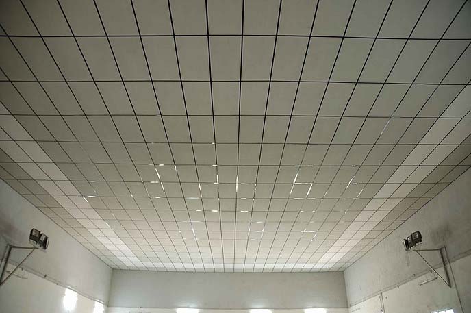
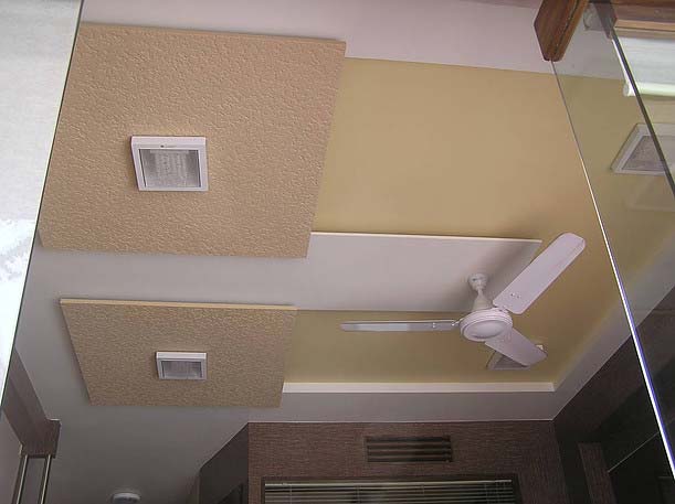
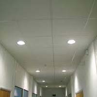
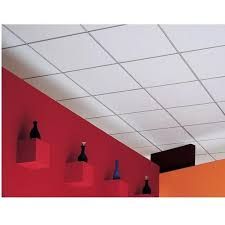
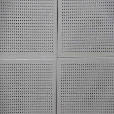
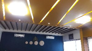
The ceiling system adopted for Bison Panel is the usual suspended ceiling system which has gained popularity in the building industry. The usual methods adopted for any other suspension ceiling also will hold good for Bison Panel. The thickness of Bison for false ceiling can be 6 mm or 8 mm depending on the requirement of thermal comfort. The false ceiling can be either ‘T’ grid type or flush jointed type. The information presented on this webpage is a general gude to good practice & is no form of warranty. The thickness of the Bison Panel for false ceiling can be 6 mm or 8 mm depending on the requirement of thermal comfort. The false ceiling can be either ‘T’ grid type or flush jointed type. In either case, the longitudinal supports shall be spaced at 610 mm intervals and cross supports at 610 mm or 1220 mm centres.
Grid System
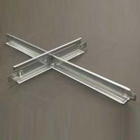
- Grid can be made either with steel or aluminium Tee sections or with timber with suitable wall line supports. The suspension arrangement can be with G.I. wires of adequate guage taken to required level from the sofit.
- Bison Panels 6 mm and 8 mm thick are recommended for false ceilings.
- The grid shall be 610 x 610 mm or 610 x 1220 mm (2’0 x 2’0 or 2’0 x 4’0.)
- In case, Aluminium T-sections are used for the grid, the minimum thickness of the section shall be 1.2 mm and size 30 x 35 mm.
- Suspenders can be either 8 swg G.I. wire or 0.7 x 12 mm G.I. flats. They are available in the market as coils.
- The maximum distance allowed between suspenders in longitudinal direction and cross direction is 1220 mm or 4’0. Closer intervals may be adopted depending on the sofit conditions.
- It is necessary to introduce a turn buckle in the suspender for easy and faster levelling of the grid. Ordinary G.I. Jbolt can serve as turn buckle.
- It is important to fix wall rest perfectly level, as the level of the entire grid depends on the level of wall rest.
- In areas where change in humidity and temperature are appreciable and frequent, it is desirable to provide a lock pin on the top of the panels to ensure structural integrity of the grid and the panel. The lock pin can be either a headless nail or a screw taken across the web of the Tee section (please refer sketch). This will avoid lifting of the Board in the grid due to thermal expansion that may take place in the material ofthe grid or the Board.
- Wherever the lighting points occur, extra suspenders will have to be provided to take the load ofthe outfits.
- The panels will have to be painted in dry condition on both sides and the ends in particular before inserting them in the grid.
- A clearance of 1-2 mm shall be given between the board and the grid on all sides for taking care of thermal expansion if any.
Fixed Ceiling
- Fix light steel box section beams 100mm X 50mm and 1.6mm / 2mm thick at 4'-0 or 1220mm intervals across the walls or suspend them by means ofsuitable clamps fixed on the sofit.
- Fix principal C studs 75 X 50 X 20 – 1.6mm thick below the beams with screws.
- Fix common studs between principal studs at 4 feet intervals with suitable clamps.
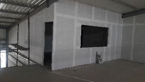
- The board will have to be fixed on principal joists as well as common joists with 3 to 5mm gap. The gap can be filled with Acrylic filler or polysulfide as the case may be.
- Provide independent principal studs at the edge of the boards.
- Painting for the board has to be done on both sides and edges.
- When timber studs are used the same procedure may be followed.


